


Grounding Resistance Measuring Instrument Selection And Testing Precautions
1. What is grounding resistance?
Based on actual research by demiks, a manufacturer of substation equipment.Grounding resistance is the resistance encountered when the current flows from the grounding device into the earth and then flows through the earth to another grounding body or spreads to a distant place. It includes the resistance of the grounding wire and the grounding body itself, the contact resistance between the grounding body and the earth's resistance, and the resistance of the earth between the two grounding bodies or the earth's resistance from the grounding body to infinity. The size of the grounding resistance directly reflects the degree of contact between the electrical device and the "ground" and also reflects the scale of the grounding network. In a single-point grounding system, strong interference and other conditions, the measurement method of the auxiliary ground level can be used for measurement. There are mainly three types of grounding resistance:
1.)Protective grounding: The metal casing of electrical equipment, concrete, poles, etc., may be charged due to insulation damage. Grounding is set up to prevent this situation from endangering personal safety.
2.) Anti-static grounding: Grounding of flammable oil, natural gas storage tanks and pipelines, electronic equipment, etc. to prevent the influence of static electricity.
3.) Lightning protection grounding: In order to introduce lightning into the ground, the grounding end of the lightning protection equipment (lightning rod, etc.) is connected to the earth to eliminate the damage of lightning overvoltage to electrical equipment, personal property, and grounding, also known as overvoltage protection grounding.
2. How to choose a grounding resistance measuring instrument:
1.) For large grounding grids (diagonal 60m), the traditional voltage-current meter method is generally used to measure the grounding resistance. When measuring, large equipment such as isolation transformers and voltage regulators are required. Its advantages are large output current (>30A), strong anti-interference ability, and high reliability of measurement results. Its disadvantages are that the equipment is bulky and difficult to carry. When measuring, the current line requires a larger cross-section (>6mm2). Generally, when measuring the grounding grid of large-scale substations and power plants in operation, this method is required to eliminate the zero-sequence current interference of the grounding grid.
2.) For small grounding grids (diagonal ≤60m), when the local interference signal is weak, a grounding shaker or a digital grounding resistance tester is generally used to measure its grounding resistance value. Its advantages are that it is easy to carry, does not require AC power supply, and is convenient for field measurement. Its disadvantages are that the output current is small and the anti-interference ability is poor. Generally, this type of instrument is mostly used when measuring the grounding body of lightning protection equipment and the grounding body of transmission line towers.
III. Several methods for measuring ground resistance
1.)Single clamp measurement
Measure the grounding resistance of each grounding point in multi-point grounding, and the grounding connection cannot be disconnected to prevent danger.
Applicable to: multi-point grounding, the connection cannot be disconnected, and the resistance of each grounding point is measured.
2.) Two-wire method
Condition: There must be a known well-grounded ground, and the measured result is the resistance of the measured ground and the known ground. If the known ground is much smaller than the resistance of the measured ground, the measurement result can be used as the result of the measured ground.
Applicable to: areas where dense buildings or cement ground are sealed and ground piles cannot be driven.
3.) Three-wire method
Condition: There must be two ground rods: an auxiliary ground and a detection electrode. The interval between each grounding electrode is 5 to 10 meters. The principle is to add current between the auxiliary ground and the ground to be measured, measure the voltage drop between the ground to be measured and the detection electrode, and the measurement result includes the resistance of the measured cable itself.
Applicable to: foundation grounding, construction site grounding and lightning protection grounding.
4.) Four-wire method
Basically the same as the three-wire method, it replaces the three-wire method when measuring low ground resistance and eliminating the influence of the measurement cable resistance on the measurement result. When measuring, E and ES must be directly connected to the ground to be measured separately. This method has the highest accuracy among all ground resistance measurement methods.
5.) Double clamp method
Conditions: multi-point grounding, no auxiliary ground piles, and single ground measurement.
Wiring: Use the current clamp specified by the manufacturer to connect to the corresponding socket, clamp the two clamps on the grounding conductor, and the distance between the two clamps should be greater than 0.25 meters.
IV. Measurement principle of ground resistance tester
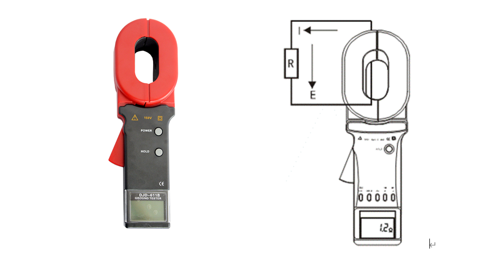
1.) Single clamp method
The basic principle of measuring ground resistance with a clamp-type ground resistance meter is to measure loop resistance. See Figure 2. The clamp part of the clamp meter consists of a voltage coil and a current coil. The voltage coil provides an excitation signal and induces an electric potential E in the measured circuit. Under the action of the electric potential E, a current I will be generated in the measured circuit. The clamp meter measures E and I, and the measured resistance R can be obtained by the following formula.
R=E/I
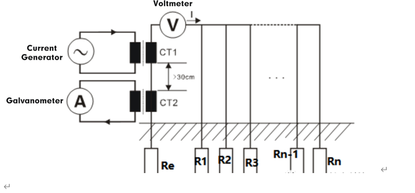
2.) Double clamp method
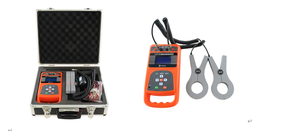
The double-clamp method measures the grounding resistance value (suitable for measurement of multiple independent points in parallel grounding system without auxiliary ground piles). An AC electromotive force V is generated by the excitation clamp CT1, and a current I is generated in the loop under the action of the AC electromotive force V. The feedback current I is then detected by CT2, and the resistance value is calculated according to the formula R=V/I. In the figure, R=Re+R1//R2//R3//…Rn-1//Rn. When R1//R2//R3//…Rn-1//Rn (the resistance value after multiple grounding points are connected in parallel) is much smaller than Re, R≈Re.
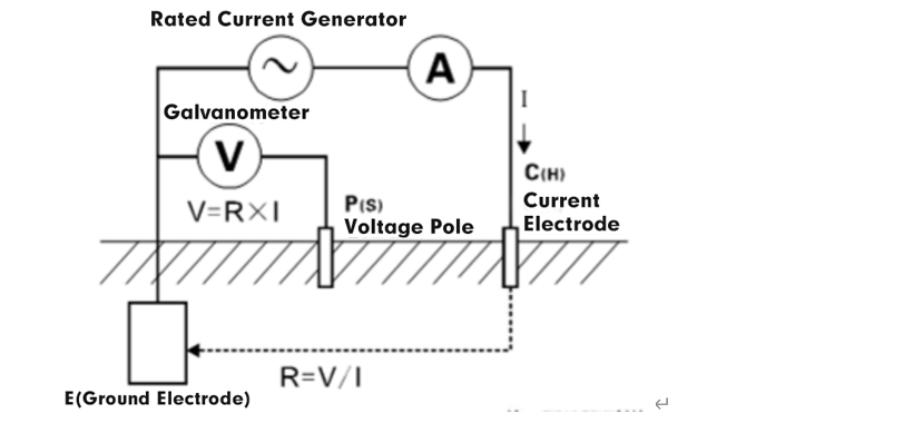
3.) Two, three, four wire
The three-wire and four-wire methods are used to measure the grounding resistance value. The rated current pole changing method (suitable for accurate measurement of single-point grounding system) is used, that is, the rated AC current I flows between the E grounding electrode and the C (H) current electrode of the measurement object, and the potential difference V between the E grounding electrode and the P (S) voltage electrode is obtained, and the grounding resistance value R is calculated according to the formula R = V/I. In order to ensure the accuracy of the test, the 4-wire method is used, and the ES auxiliary ground electrode is added. In actual testing, ES and E are clamped at the same point of the grounding body.
V. Precautions for measuring grounding resistance
(1) When measuring grounding resistance with an AC power supply during the test, an independent power supply should be used, usually a separate transformer, and the neutral and grounding points should be opened to prevent errors caused by shunting or failure to raise the current. The voltage level is estimated based on the impedance of the current loop and the current required to be raised.
(2) In many substations, the overhead ground wire of the transmission line is connected to the substation grounding device, which will affect the measurement result of the grounding resistance of the substation grounding device. Therefore, the lightning protection wire of the overhead line should be disconnected from the electrical connection of the substation grounding device before measurement.
(3) Since a large current is injected into the current pole, it will cause harm to nearby people and animals. Therefore, a dedicated person should be on guard during the measurement.
(4) During the test, the current lead will flow a large current, so the current loop should have a larger conductor cross-section.
VI. Measures to eliminate interference in grounding resistance measurement:
1) Eliminate interference from zero-sequence current on the grounding body
Due to unbalanced load, there is always some zero-sequence current flowing through the grounding body in the high-voltage outgoing lines of power plants and substations. When these currents flow through the grounding device, a voltage drop will be generated on the grounding device, which will cause errors in the measurement results. It is often necessary to increase the value of the measured current to eliminate the influence of stray current on the measurement results.
In order to improve the test accuracy, the most effective way is to increase the test current to reduce the proportion of the zero-sequence current component. Therefore, the "Measurement Guidelines" stipulates: "The test current passing through the grounding device is large, the zero-sequence current and interference voltage in the grounding device have little influence on the measurement results, and the range of the measurable current field of the voltmeter with the same resolution is large, that is, the actual measured value error of the power frequency grounding resistance is small. In order to reduce the error of the actual measured value of the power frequency grounding resistance, the test current passing through the grounding device should not be less than 30A". It can be seen that increasing the test current is the most effective measure to reduce zero-sequence current interference.
2) Eliminate the interference of lead mutual inductance on measurement
When the current-voltage method is used to measure ground resistance, the mutual inductance of the leads will affect the measurement results because the voltage line and the current line are placed together at a long distance. In order to eliminate the influence of the mutual inductance of the leads, the following measures are usually adopted.
(1) The electrodes are arranged using the triangle method. When the triangle is arranged, the voltage line and the current line are far apart, and the mutual inductance is small, which will not cause a big impact.
(2) When using the overhead line with power outage and arranging the electrodes in a straight line, an overhead line can be used as the current line, and the voltage line should be arranged along the ground. The two should be 5-10m apart.
(3) The four-pole method can eliminate the influence of the mutual inductance of the leads. In addition, the voltage, current meter and power meter method can be used for measurement.
Conclusion: The ground resistance tester is currently commonly used in electrical safety inspection and grounding project completion acceptance, involving multiple fields such as power, telecommunications, meteorology, oil fields, construction, lightning protection and industrial electrical equipment. It is a commonly used measurement tool for specific indicators such as ground resistance, soil resistivity, ground voltage, AC current, leakage current, etc. Choosing a suitable ground resistance tester and mastering the correct use method are of great significance to ensure the safe operation of equipment and prevent electrical accidents. The above is the sharing of Shanghai Demiks Power Test Engineer. I hope it can help everyone better understand the selection and use of ground resistance testers and provide strong support for practical work.
The above content by demiks finishing released, reproduced please specify, demiks is a substation equipment manufacturers, specializing in the production of partial discharge test, transformer test equipment, circuit breaker test equipment, relay tester, SF6 gas analyser, cable fault tester and other products, such as electric power testing and inspection needs please feel free to contact demiks power science and technology limited company or send an email! to us: contact@demikspower.com
 Relay Protection Testing and Commissioning Gu
 how to test microwave transformer
 how to reset circuit breaker with test button
 high voltage cable testing standards