

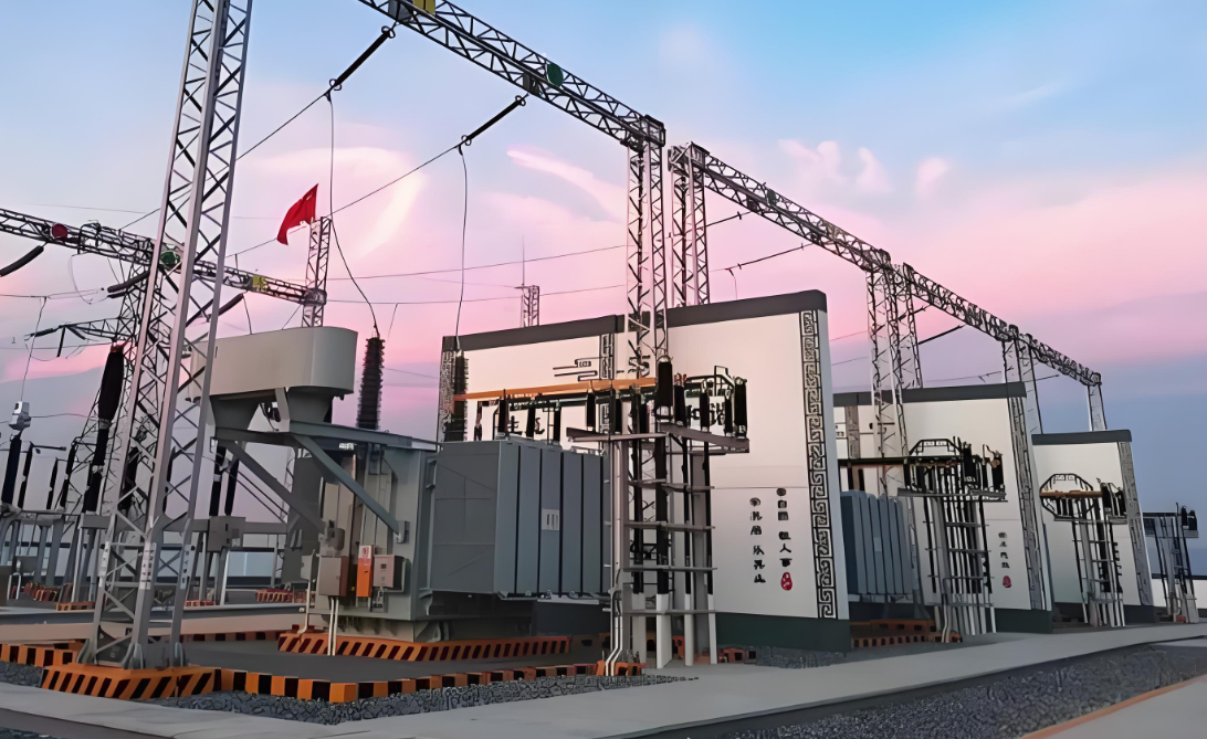
Step-by-step process of substation construction
Constructing an electrical substation involves careful planning, engineering, and execution to ensure safety, reliability, and compliance with standards. Below is a detailed breakdown of the substation construction process, covering site selection, design, equipment installation, and commissioning.
1. Site Selection & Preparation
Key Considerations:
✔ Proximity to Load Centers – Minimizes transmission losses.
✔ Accessibility – Easy transport of heavy equipment (transformers, switchgear).
✔ Geotechnical & Environmental Factors – Stable soil, flood risk, seismic zone.
✔ Clearance & Safety – Adequate space for maintenance and future expansion.
Site Preparation Steps:
Land Clearing & Grading – Leveling the ground.
Soil Testing – Ensures foundation stability.
Fencing & Security – Prevents unauthorized access.
2. Substation Design & Layout
Types of Substations:
Air-Insulated Substation (AIS) – Outdoor, uses air as insulation.
Gas-Insulated Substation (GIS) – Compact, SF6 gas-insulated.
Hybrid Substation – Combination of AIS and GIS.
Key Design Components:
Single-Line Diagram (SLD) – Shows electrical connections.
Layout Plan – Positions transformers, switchgear, busbars, control room.
Earthing System – Grounding grid for safety and fault current dissipation.
Lightning Protection – Lightning masts/arresters.
3. Civil & Structural Work
A) Foundation Construction
Transformer Foundation – Reinforced concrete with oil containment.
Switchgear & Control Room – Concrete slab with cable trenches.
Gantry & Busbar Supports – Steel structures for overhead busbars.
B) Cable Trenches & Ducts
Underground conduits for power and control cables.
C) Drainage System
Prevents waterlogging (critical for oil-filled equipment).
4. Equipment Installation
A) Power Transformers
Transport & Placement – Heavy cranes required.
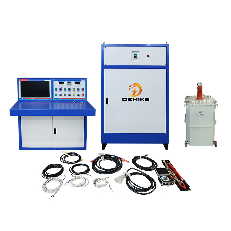
Oil Filling & Testing – Insulation resistance, turns ratio, DGA.
B) Switchgear (Circuit Breakers, Isolators, CT/PT)
HV Circuit Breakers (VCB, SF6, Oil).
Disconnectors (Isolators) – For maintenance isolation.
Current & Voltage Transformers (CT/PT) – For metering & protection.
C) Busbars & Conductors
Rigid Busbars (Aluminum/Copper) for indoor substations.
Strain Bus (Flexible conductors) for outdoor AIS.
D) Control & Protection Systems
Relay Panels (Overcurrent, differential, distance protection).
SCADA & Communication Systems – Remote monitoring.
E) Earthing & Lightning Protection
Grounding Grid – Copper/steel mesh buried underground.
Lightning Arresters – Rod gaps or surge arresters.
5. Cable Laying & Termination
Power Cables (XLPE, Oil-filled) – Terminated at bushings.
Control Cables – Connected to relay panels.
Testing – Insulation resistance, hi-pot, continuity.
6. Testing & Commissioning
Before energizing, perform:
✔ Insulation Resistance Test (Megger test).
✔ Transformer Turns Ratio (TTR) Test.
✔ Circuit Breaker Timing & Contact Resistance Test.
✔ Relay Calibration & Secondary Injection Test.
✔ Primary Injection Test (High-current testing).
✔ Polarity & Phase Sequence Check.
7. Energization & Handover
Gradual Voltage Application – First LV, then HV.
Load Testing – Verify performance under real conditions.
Documentation – As-built drawings, test reports, O&M manuals.
Key Standards for Substation Construction
IEC 61936 (Design & safety).
IEEE 80 (Grounding systems).
NFPA 70 (NEC) & IEC 62271 (Switchgear standards).
Challenges in Substation Construction
Heavy Equipment Logistics – Transporting large transformers.
Environmental Compliance – Oil spill prevention, noise control.
Grid Synchronization – Ensuring compatibility with existing networks.
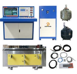
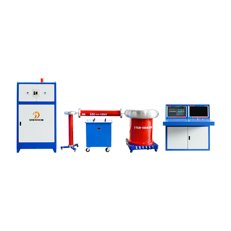
The above content is published by demiks, please specify, demiks is a substation equipment manufacturer, specializing in the production of high-voltage tester, transformer tester, circuit breaker test equipment, relay tester, SF6 gas analyser, cable fault tester and other products, if you have power test testing needs, please feel free to contact demiks power science and technology limited company or send an email! Give us: contact@demikspower.com
 Relay Protection Testing and Commissioning Gu
 how to test microwave transformer
 how to reset circuit breaker with test button
 high voltage cable testing standards