


Three Phase Transformer Winding Resistance Test Procedures and Guidelines
Winding resistance testing is a critical diagnostic test for transformers, helping detect:
Loose connections
Broken strands in windings
Contact issues in tap changers
Imbalance between phases
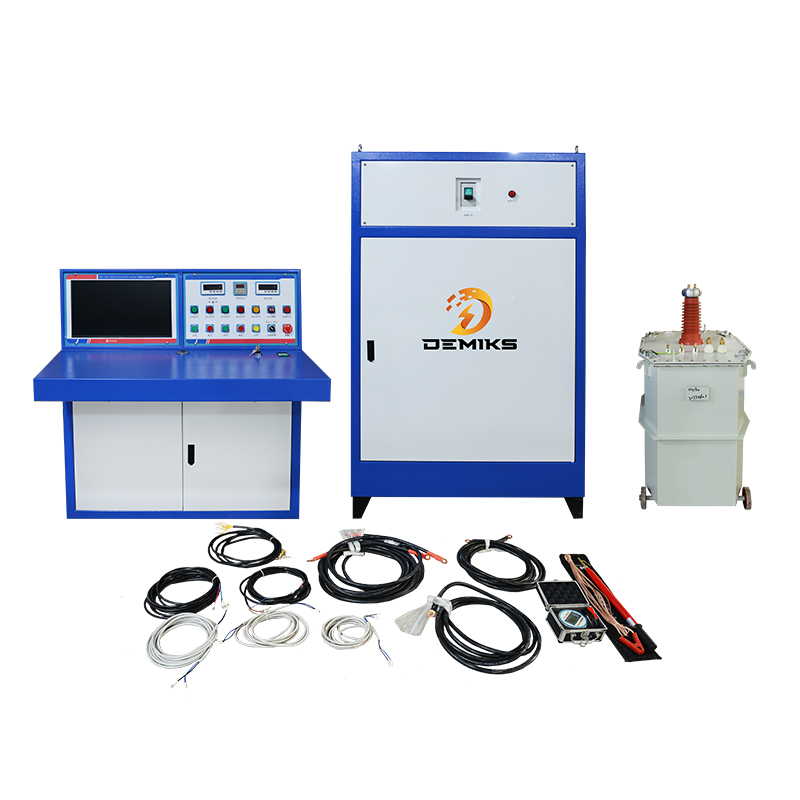
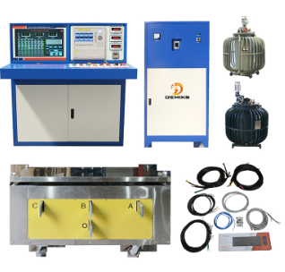
1. Test Equipment
Micro-ohmmeter (preferred, with 1µΩ resolution)
Kelvin Bridge (DC resistance bridge)
Temperature sensor (for correction to 20°C)
Test leads with high-current clamps
2. Test Procedure
Step 1: Safety Precautions
✔ De-energize the transformer and ground windings.
✔ Discharge stored energy (inductive kickback).
✔ Verify lockout/tagout (LOTO).
Step 2: Connections
Star (Wye) Windings:
Measure phase-to-neutral (if accessible) or phase-to-phase and calculate phase resistance.
Delta Windings:
Measure phase-to-phase and use formulas to derive individual phase resistances.
Connection Diagram
       R1                          R2
       ▲                            ▲
       │                            │
       └────[Transformer]────┘
       ▲                            ▲
       │                            │
       R3                          (Neutral, if Wye)
Step 3: Apply DC Current & Measure
Inject 10–50% of rated current (to avoid heating).
Wait for stabilization (typically 1–5 minutes).
Record resistance (R) + temperature (T).
Step 4: Temperature Correction
Convert readings to 20°C for comparison:
R20°C=Rmeasured×234.5+T234.5+20(For copper windings; use 225 for aluminum)
Step 5: Compare Results
Acceptance Criteria (IEEE C57.12.90):
Deviation ≤ ±2% between phases.
Match factory data within ±5%.
3. Common Issues & Troubleshooting
| Issue | Possible Cause | Solution |
|---|---|---|
| High Resistance | Loose connections, broken strands | Check joints, retorque bolts |
| Low Resistance | Shorted turns | Perform TTR (Turns Ratio Test) |
| Unbalanced Phases | Tap changer misalignment | Inspect OLTC/MOLTC contacts |
4. Standards & Best Practices
IEEE C57.12.90 (Transformer Testing)
IEC 60076-1 (Power Transformers)
Test at multiple tap positions (for OLTC transformers).
Use 4-wire (Kelvin) method to eliminate lead resistance errors.
5. Example Measurement (11kV/433V Transformer)
| Winding | Measured (µΩ) | Temp (°C) | Corrected (20°C, µΩ) |
|---|---|---|---|
| Phase R | 540 | 30 | 515 |
| Phase Y | 545 | 30 | 520 |
| Phase B | 550 | 30 | 525 |
| Deviation | < 2% ✅ |
Key Takeaways
✅ Detects winding defects before failure.
✅ Must be temperature-corrected for accuracy.
✅ Unbalance >2% indicates a problem.
The above content is published by demiks, please specify, demiks is a substation equipment manufacturer, specializing in the production of high-voltage tester, transformer test equipment, circuit breaker test equipment, relay tester, SF6 gas analyser, cable fault tester and other products, if you have power test testing needs, please feel free to contact demiks power science and technology limited company or send an email! Give us: contact@demikspower.com
 Relay Protection Testing and Commissioning Gu
 how to test microwave transformer
 how to reset circuit breaker with test button
 high voltage cable testing standards