


Detection Methods and Basic Measurement Circuits for Partial Discharge
Partial discharge testing refers to the phenomenon of small-scale corona discharges occurring in electrical insulation systems, which can lead to damage to the insulation system and ultimately to equipment failure. Based on the various physical phenomena that occur during partial discharges, the
Testing Methods:
1. Electric test Methods
In engineering, there are three methods for electric test.
1. Radio Interference Voltage Method (RIV);
2. Impulse Current Method (ERA);
3. Ultra-High-Frequency Electromagnetic Wave Method (UHF).
2. Non-Electrical test Methods
There are also three non-electrical test methods:
1. Acoustic Test: Measure sound waves or ultrasonic waves;
2. Optical Test: Measure infrared rays, ultraviolet rays or visible light.;
3. Gas Test: Measure and analyzer specific substances in the insulation system.
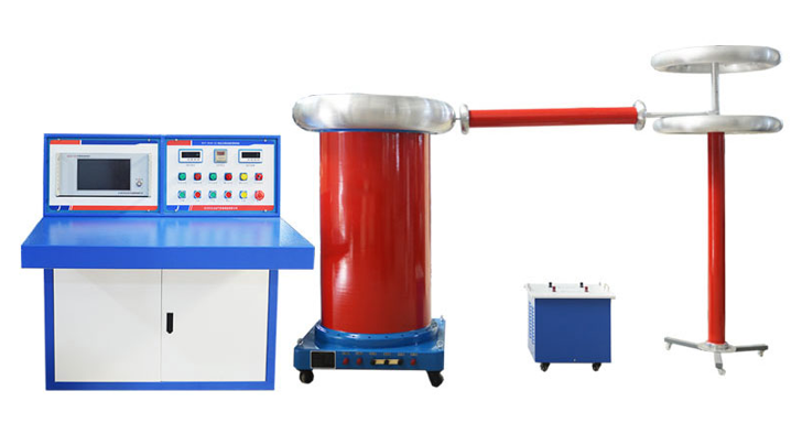
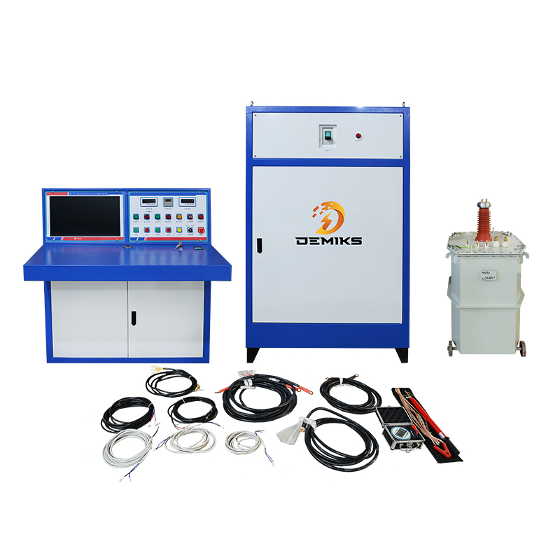
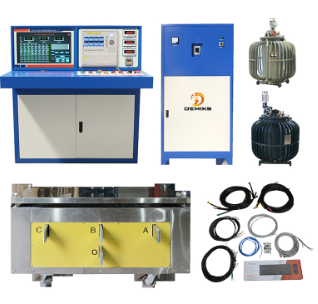
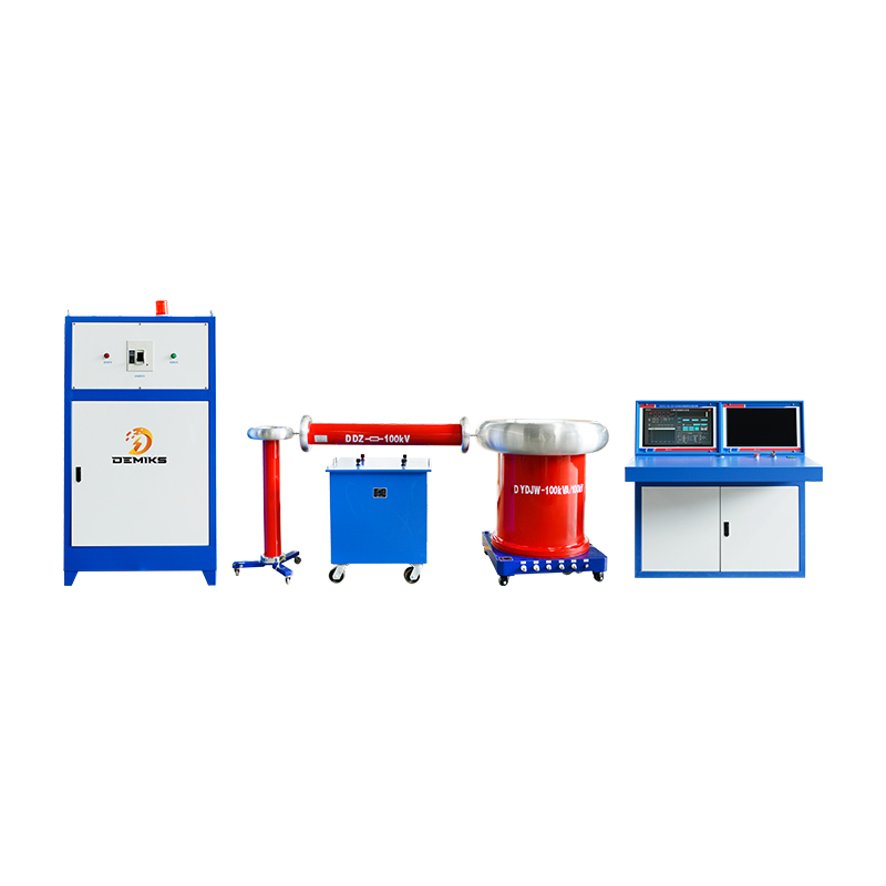
Components of Partial Discharge Test System
A partial discharge test system consists of four parts: measurement instrument, coupling device, calibration device, and transmission system.
Propagation and Sampling of Partial Discharge Signals
Propagation Paths of Partial Discharge Signals in Transformer:
1. Impulse current (LC transmission circuit);
2. High-frequency electromagnetic waves;
3. Ultrasonic waves.
Partial Discharge Signal Sampling Methods:
- Broadband current transformer;
- Antennas;
- Ultrasonic sensors.
Basic test Circuit for Partial Discharge
The basic test circuits for partial discharge test use the impulse current method (ERA method) are divided into two categories: direct method and bridge method (balanced method). The direct method further includes parallel test circuits and series test circuits.
- (a) and (b) are direct method test circuits:
- (a) Parallel test circuit;
- (b) Series test circuit.
- (c) balance method test circuit.
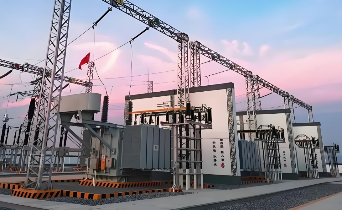
Importance of Basic Partial Discharge Measurement Circuits
Early Warning: Detects partial discharge signals to identify potential equipment issues in advance.
Enhanced Reliability: Ensures the safe and stable operation of power equipment.
Reduced Maintenance Costs: Minimizes equipment failures and downtime.
The above content is published by demiks, please specify, demiks is a substation equipment manufacturer, specializing in the production of high-voltage tester, transformer test equipment, circuit breaker test equipment, relay tester, SF6 gas analyser, cable fault tester and other products, if you have power test testing needs, please feel free to contact demiks power science and technology limited company or send an email! Give us: contact@demikspower.com
 Relay Protection Testing and Commissioning Gu
 how to test microwave transformer
 how to reset circuit breaker with test button
 high voltage cable testing standards