


What are the procedures for testing high voltage cables
High-voltage cables must be tested regularly with a high-voltage tester to ensure insulation integrity, reliability and safety during transmission and distribution. Proper testing helps to detect partial discharges, insulation degradation and installation faults before they occur.
1. Types of High Voltage Cable Tests
A. Routine Tests (Factory & On-Site)
Insulation Resistance Test (Megger Test)
DC Hi-Pot (High Potential) Test
Partial Discharge (PD) Test
Tan Delta (Dissipation Factor) Test
VLF (Very Low Frequency) Test
B. Diagnostic Tests (Condition Monitoring)
Time Domain Reflectometry (TDR) for Fault Location
Sheath Integrity Test (For Metallic Sheathed Cables)
Impulse Testing (Surge Testing)
2. Step-by-Step HV Cable Testing Procedure
A. Pre-Test Safety Checks
✔ De-energize the cable and follow LOTO (Lockout-Tagout) procedures.
✔ Verify proper grounding before testing.
✔ Use appropriate PPE (insulated gloves, safety barriers).
✔ Check test equipment calibration status.
B. Insulation Resistance Test (Megger Test)
Purpose: Measures insulation quality (in MΩ).
Equipment: Insulation resistance tester (5kV or 10kV Megger).
Procedure:
Disconnect cable from both ends (switchgear & transformer).
Discharge any residual voltage using a grounding rod.
Connect the Megger:
Line terminal → Cable conductor.
Earth terminal → Cable sheath/armor.
Apply test voltage (typically 500V to 10kV DC) for 1 minute.
Record insulation resistance value (should be > 1000 MΩ/km for new cables).
Discharge the cable after testing.
Acceptance Criteria:
> 100 MΩ (Older cables)
> 1000 MΩ (New cables)
C. DC High Potential (Hi-Pot) Test
Purpose: Checks insulation strength under high DC voltage.
Equipment: DC Hi-Pot tester (up to 2x rated voltage).
Procedure:
Ensure cable is fully discharged.
Connect:
Positive terminal → Cable conductor.
Negative terminal → Ground/sheath.
Gradually increase voltage (step-up method):
Step 1: 25% of test voltage, hold for 1 min.
Step 2: 50% of test voltage, hold for 1 min.
Step 3: 75% of test voltage, hold for 1 min.
Step 4: 100% of test voltage, hold for 15 min.
Monitor leakage current (should stabilize).
If current spikes or breakdown occurs, stop the test.
Test Voltage (IEC 60502 Standard):
| Cable Rating (kV) | Test Voltage (DC, kV) |
|---|---|
| 11 kV | 22 kV (2x rated) |
| 33 kV | 66 kV |
Acceptance Criteria:
No breakdown or sudden current surge.
Leakage current should stabilize (no continuous rise).
D. Very Low Frequency (VLF) Test
Purpose: Detects insulation defects using 0.1 Hz AC (alternative to DC Hi-Pot).
Equipment: VLF tester (up to 3x rated voltage).
Procedure:
Connect VLF tester to the cable conductor.
Apply 0.1 Hz AC voltage in stages (similar to Hi-Pot).
Hold at final voltage (3U₀) for 15-60 min.
Monitor tan delta (dissipation factor) for insulation health.
Advantages:
Less damaging than DC for aged cables.
Detects water trees & partial discharges.
E. Partial Discharge (PD) Test
Purpose: Locates internal voids or defects in insulation.
Equipment: PD detector, coupling capacitor, HV source.
Procedure:
Apply AC voltage slightly above operating level.
Use high-frequency CT sensors to detect PD signals.
Analyze PD magnitude (pC) and phase-resolved patterns.
Acceptance Criteria:
< 10 pC (New cables)
< 100 pC (Older cables, monitor trend)
F. Tan Delta (Dissipation Factor) Test
Purpose: Measures insulation dielectric losses.
Equipment: Tan delta bridge, HV source.
Procedure:
Apply AC voltage at power frequency (50/60 Hz).
Measure loss angle (δ) and calculate tan δ = (Iᵣ/I꜀).
Acceptance Criteria:
< 0.5% (Healthy insulation)
> 1% (Degraded insulation – further investigation needed)
3. Common Faults Detected
✔ Insulation breakdown (Hi-Pot test failure).
✔ Water ingress (VLF/Tan Delta test).
✔ Partial discharges (PD test).
✔ Shield/sheath damage (TDR test).
4. Safety Precautions
⚠ Always discharge cables before & after testing.
⚠ Use proper grounding to avoid residual voltage hazards.
⚠ Follow IEEE 400 & IEC 60502 standards.
⚠ Never exceed recommended test voltages.
Conclusion
Regular HV cable testing ensures long-term reliability and prevents unexpected failures. Key tests include:
✅ Megger (Insulation Resistance)
✅ DC Hi-Pot (Dielectric Strength)
✅ VLF (Aged Cable Testing)
✅ Partial Discharge (Early Fault Detection)
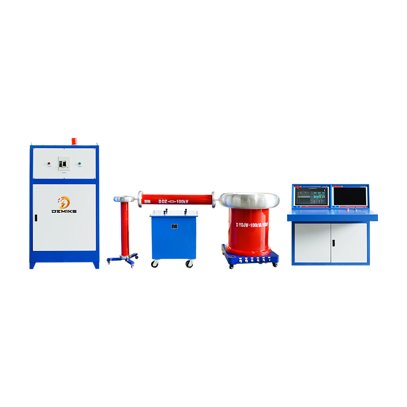
The above content is published by demiks, please specify, demiks is a substation equipment manufacturer, specializing in the production of high-voltage tester, transformer tester, circuit breaker test equipment, relay tester, SF6 gas analyser, cable fault tester and other products, if you have power test testing needs, please feel free to contact demiks power science and technology limited company or send an email! Give us: contact@demikspower.com
 Relay Protection Testing and Commissioning Gu
 how to test microwave transformer
 how to reset circuit breaker with test button
 high voltage cable testing standards